
After careful material quantity calculations, (the Journal of Light Construction Field Guides, listed under the resources section of this blog, gives a great method for calculating rough framing lumber quantities), I went to the lumberyard and placed my order. I also placed an order for fencing material, as I will be concurrently building a fence to enclose our backyard (as I would learn, not a good idea to tackle two substantial projects at once). The lumber arrived on a Wednesday, forcing me to curb my enthusiasm to start framing for two more days. I spoke to my grandfather on that first Saturday morning of framing, and he reveled in the idea of swinging a hammer in the fresh autumn air and abundant sunshine. It was indeed a good day to start framing.
With building permit in hand, I was able to begin the rough framing.
I majored in physics in college, and as the framing lumber was deposited in our alleyway, I couldn’t help but consider the second law of thermodynamics: entropy (disorder) naturally increases in a system unless work is done to the system. In other words, a process left to its own devices will typically become less organized and more chaotic. It’s not one’s fault that one’s bedroom or laundry room is a mess…it is a law of thermodynamics! Why fight it? I have tried in vain to use this explanation with my wife to explain the mess in our backyard during this process…“it’s not my fault, it’s the natural order of things!” The beautifully arranged pile of lumber was about to become substantially less so. However, all of the work done to the system would, hopefully, result in a more complex and ordered arrangement of the raw materials by the time of the final inspection by the city.

Framing material delivered to site
I was impressed that the lumberyard arranged the pallet of lumber in a logical way, such that the items I would need first were placed on top. The treated sill plates, for example, were on top. Just below were the 2×6 studs. To the side of those, and equally as accessible, were the 2×12 members that would be used for the headers, and finally, the top plate material. All of this was resting on the sheathing that would be used on the walls and roof. Perhaps this is normal and expected on the jobsite – either way, I was impressed with this display of forethought and efficiency, and the respect for the valuable time of the framing crew. Who would want to pay someone to sort through framing lumber just to get to the items one needs first? I could see how a thoughtless and unorganized delivery of lumber would eat into a GC’s profit margin.
In normal platform framing (the type of framing most commonly used in the United States for house framing), one usually builds the walls right on the “deck,” or the floor of the house. The foundation is poured, a sill plate is fastened to the anchor bolts sticking out of the foundation, the floor joists or trusses are set on the sill plate, and the sub-floor laid down on top. The walls are then built laying flat on the floor, with a sole plate, studs, and a single top plate. It would then be tilted up into place and anchored to the deck. In the studio construction, however, I was not installing floor joists and a deck. Instead, the walls would rest directly upon the course of concrete block. This complicated the wall construction slightly, as I would need to build the walls and then lift them onto the course of concrete block while aligning the holes for the anchor bolts in the sill plate (recall from an earlier post my perception problem with my wife’s lifting ability, and the bonding that happened during demolition…my perception problem continued here…“of course you can help me tilt up a 16′ section of wall!”).
I needed to determine a layout that would most efficiently use the sill plates I ordered (16’ lengths). As an added constraint, the building code requires at least two anchor bolts per length of wall, and requires an anchor bolt located between 4-12” from the end of a wall. Although my concrete contractor placed anchor bolts on a regular pattern, there were invariably places where I needed one and didn’t have one. In these instances, I had two choices: I could either modify the layout of my sill plates and walls such that I incorporated the correct number of anchor bolts in the correct location on each wall section, or I could erect the wall and come back later and add anchor bolts with a hammer drill and epoxy. I choose the latter. It seemed more straightforward, limited the number of wall sections in any length of wall, and would allow me to use my lumber in the most efficient manner.
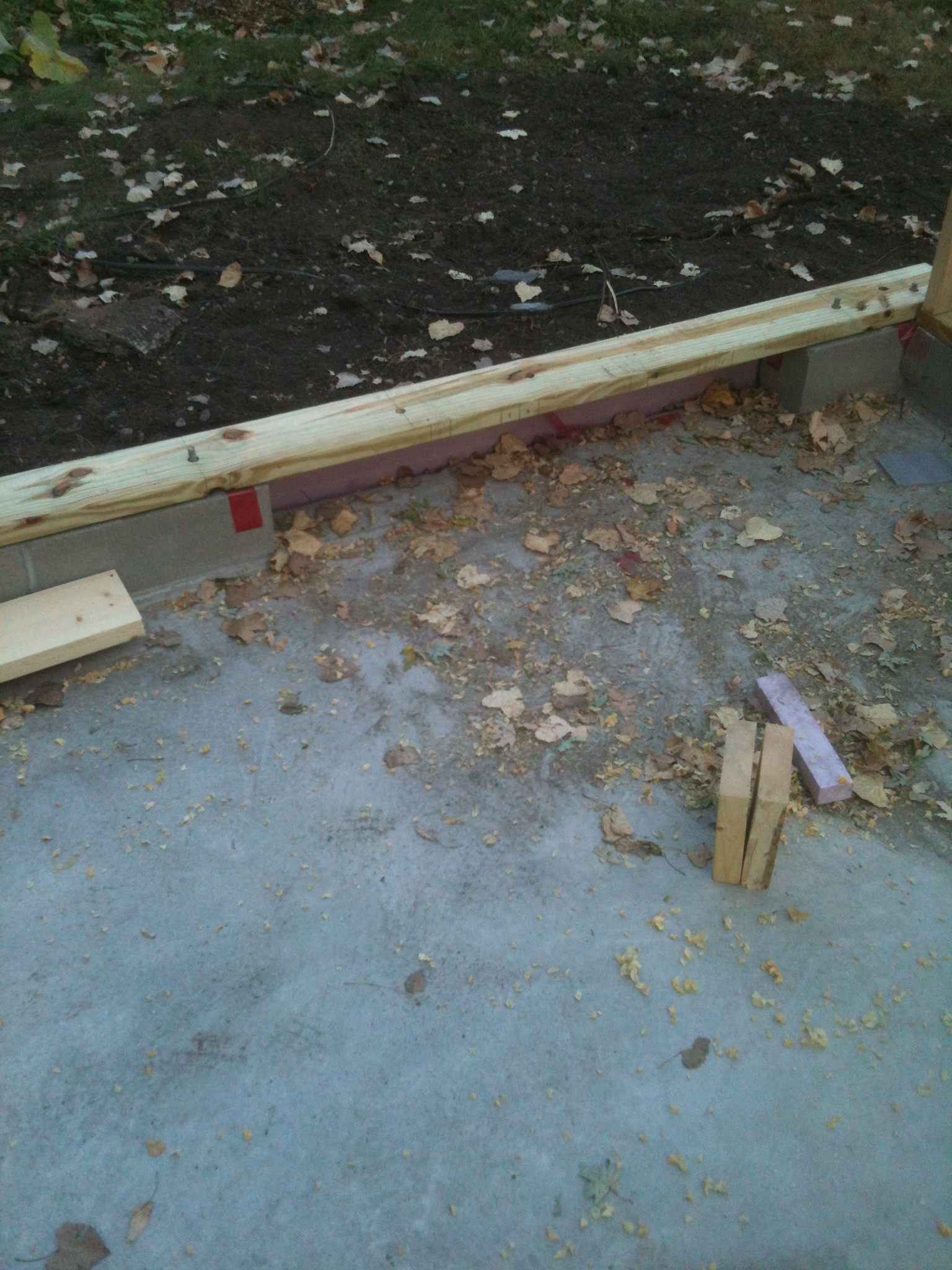
Laying out the sill plates. I ran the sill plate long over the door opening in the masonry so that I could continue the stud layout unbroken and would be able to lift the wall section in place without too much difficulty and torquing of the wall. I will cut the extra length of sill plate out once the wall is in place.
With an efficient wall section layout determined, I laid the treated sill plate on top of the course of concrete block and used my speed square to transfer the locations of the galvanized anchor bolts sticking out of the top of the course of concrete masonry units to the treated sill plates. At each location, I drilled out a 3/4″ diameter hole in the sill plate to allow the anchor bolts to pass through. I test fit each piece to make sure that they fit, and then removed plates and placed them on the slab for use in the construction of the wall.
(Any wood that is in direct contact with the earth or concrete is required to be pressure treated – that is, the wood is impregnated under high pressure with a chemical preservative that prevents rot, decay and discourages insects from feasting. This treatment imparts a wonderful green hue to the wood and makes it toxic to work with – one should always use gloves and wear a dust mask).
I then cut a top plate to match the length of the sill plate. Using a speed square, I marked out where each stud was going to go, including, around windows and doors, each king and jack stud. I did this marking with both the sill and top plate held together, so that I could be absolutely certain that the marks on each lined up and that as long as each wall section was square, each stud would be perfectly plumb. After the marks were recorded, I separated the top and sill plates and placed the various framing members in place. With a 2×6 wall, the code requires three 16d nails at both the top and bottom of the stud. This is where the framing nailer and an air compressor come in handy, and where, I suspect, framers develop one set of arm musculature more than the other.
When each wall section was assembled, I stretched a tape measure diagonally across the section, noted the measurement, and did the same along the opposite diagonal. By adjusting (kicking, pulling, yelling) the wall section at the corners until both measurements were the same, I was able to square up the entire section. Wanting to keep the wall section as light as possible (in order to effectively utilize my wife as a helper in the lifting of the wall into place), I tacked a 2×4 diagonally across the wall section to hold it square as opposed to the more traditional and time-saving method of attaching the sheathing to the wall while it laid on the ground.
With the wall section squared and tacked off, we slowly raised it and set it on top of the block. Careful measuring and double/triple/quadruple checking ensured that each wall section slid onto the anchor bolts with no resistance. After the wall sections were in place, I went around the perimeter and added the second top plate. By lapping the second top plate over the seams of the first, the walls are tied together and the entire system gains more rigidity and strength.
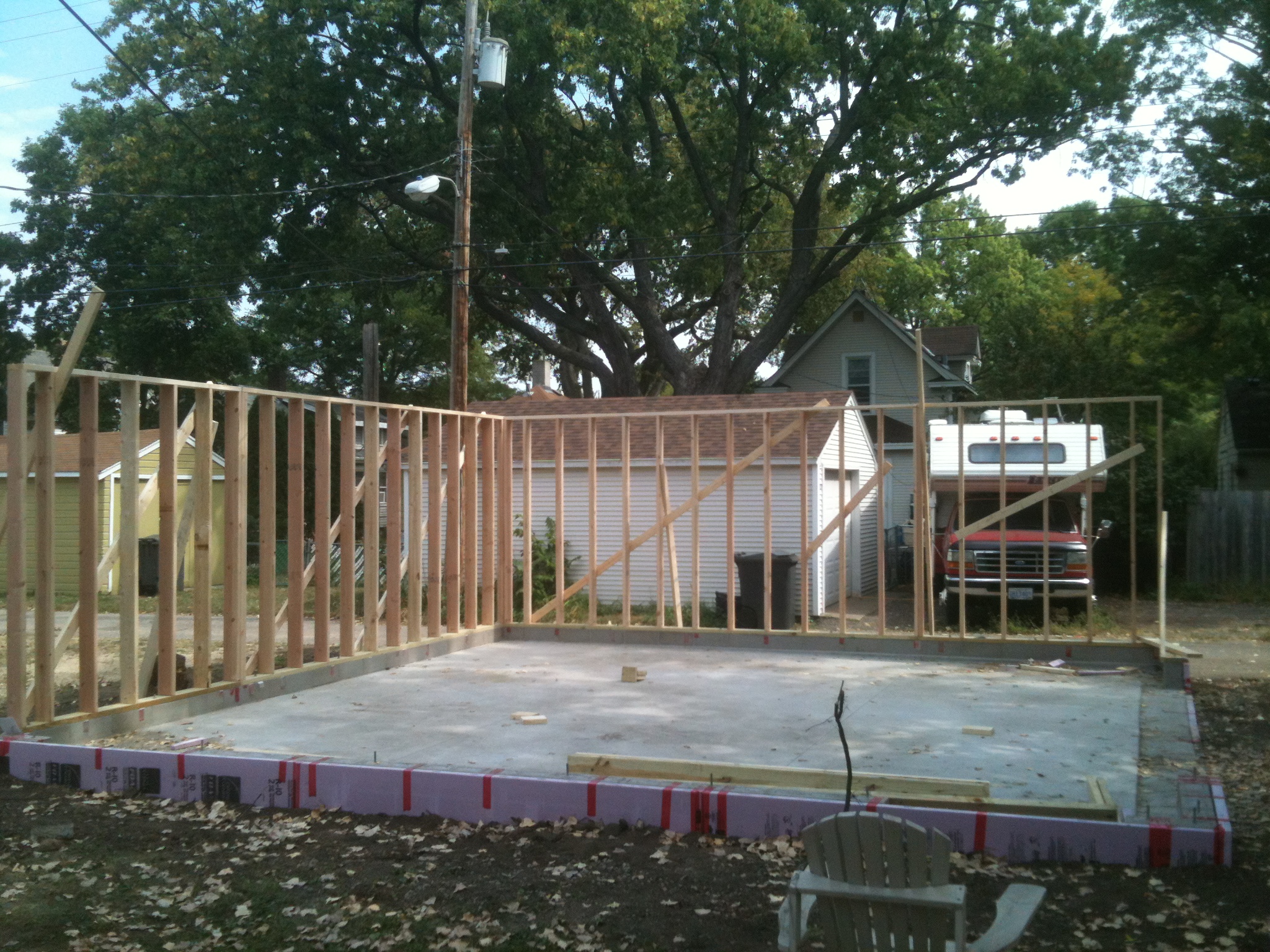
First sections of wall in place
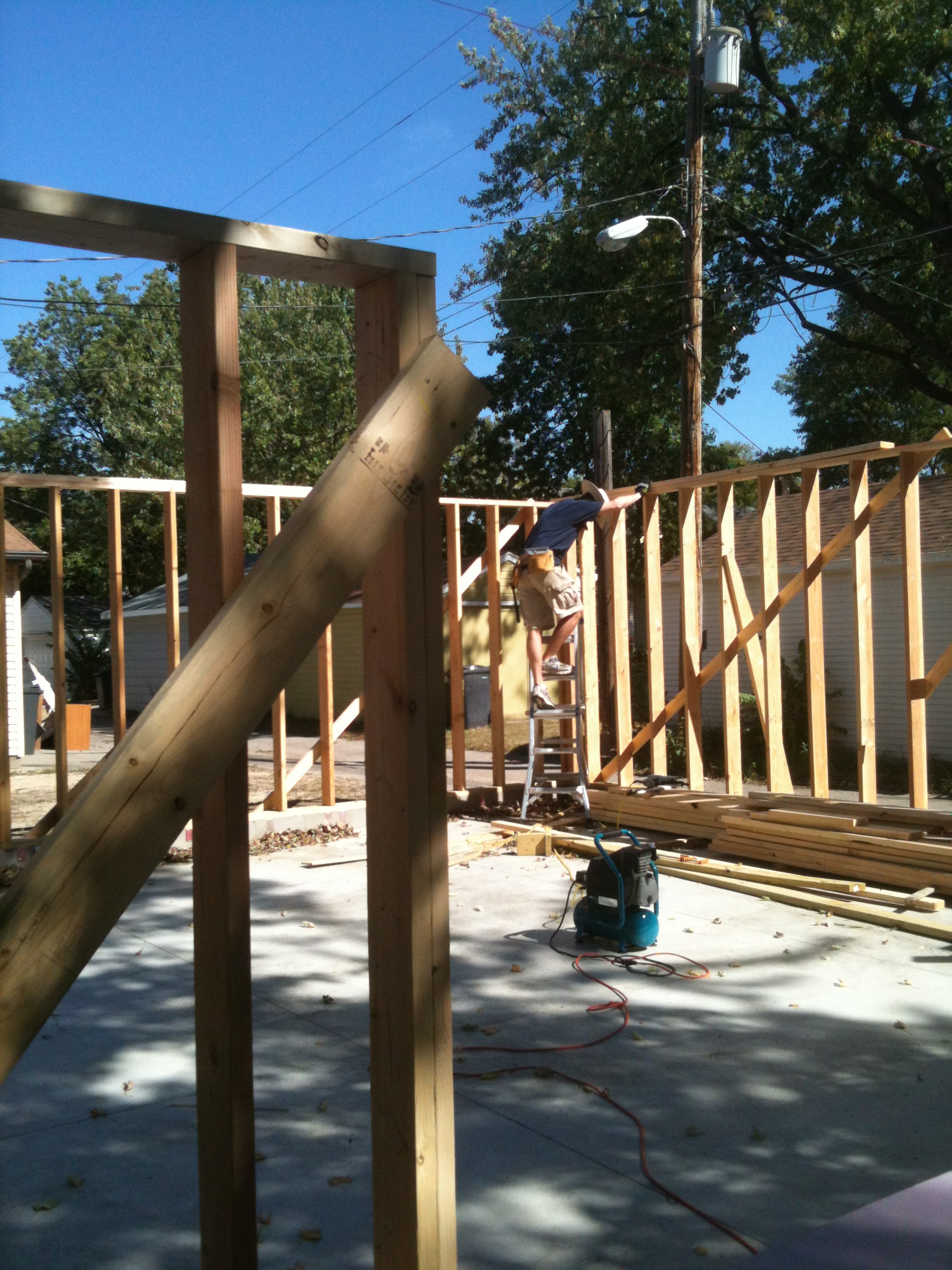
Attaching the second top plate to tie the walls together

Temporary wall bracing… certainly not OSHA compliant


The framing of the perimeter walls (less the 20′ garage header and roof trusses) required about two weekends’ worth of effort.
